
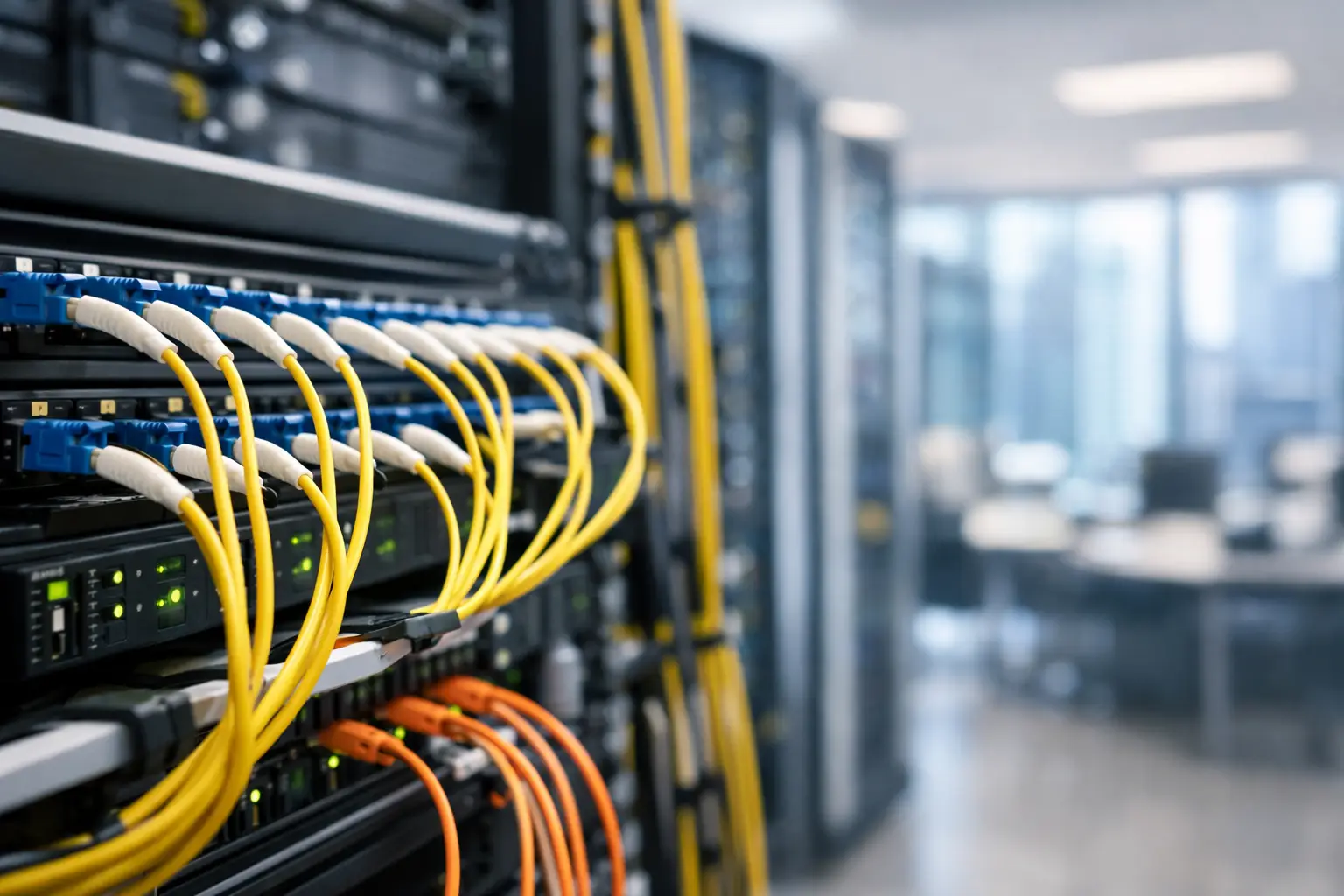
A fiber backbone is easy to ignore when the walls are closed, tenants are connected, and the network appears to work. That is exactly why fiber backbone design for commercial buildings needs disciplined ownership before construction begins. A poorly planned backbone may carry traffic on day one, yet still create years of exposure: stranded pathways, undersized telecom rooms, undocumented splices, limited carrier options, and outages that take too long to isolate.
For a commercial owner or operations leader, the question is not simply how much fiber to install. The real question is whether the building has a physical communications system that can support tenant demands, security systems, wireless coverage, building controls, and future technology without requiring repeated demolition or emergency work.
The Backbone Is a Building System, Not an IT Afterthought
The fiber backbone connects the spaces where technology enters, terminates, distributes, and operates. Depending on the property, that can include an entrance facility, main telecom room, intermediate telecom rooms, tenant distribution areas, data rooms, security command spaces, and rooftop or remote-building equipment locations.
Treating these connections as a cabling contractor's isolated scope creates a familiar problem. The contractor installs what is shown, the network team connects active equipment later, the security integrator adds cameras and access control afterward, and facilities inherits rooms it did not help design. Each party may complete its assigned work. No one has verified that the finished system supports the building as an operating environment.
A backbone design should account for the actual services expected to depend on it. That includes enterprise network traffic, tenant connectivity, Wi-Fi, cameras, access control, intercoms, audiovisual systems, distributed antenna systems, building automation, energy monitoring, and sometimes life-safety-related interfaces. These systems do not always share the same network, but they often compete for the same rooms, pathways, power, cooling, and documentation.
The result should be one standard and one accountable record of how the physical layer supports each critical service.
Start With Risk and Growth, Not a Fiber Count
A design based only on today's port requirements often becomes obsolete before a project reaches steady operation. Fiber itself has a long service life. The difficult and expensive work is creating the pathways, sleeves, risers, firestopping, and access needed to pull or replace it.
That is why backbone capacity decisions should begin with a practical assessment of the building's likely operating model. A small owner-occupied office has different needs than a multitenant tower, medical office building, distribution facility, mixed-use property, or high-availability corporate site. There is no universal strand count that fits every building.
Ask where growth will occur and what failure would mean. Will tenants expect multiple carrier choices? Is the property likely to add intelligent building systems? Will a security operations center require video from every floor? Are there separate networks for corporate IT, operations technology, and tenant services? Is the building part of a portfolio that needs consistent standards across locations?
The answers shape capacity, route diversity, enclosure locations, and separation requirements. They also identify where spending more during construction prevents much larger costs later.
A useful design distinguishes between capacity and resilience. Adding extra strands creates capacity. Providing physically diverse routes creates resilience. A 144-strand cable installed in one riser is still vulnerable to one construction incident, water event, fire, or accidental cut. For systems that cannot tolerate that single point of failure, the design needs separate pathways or risers, separate entrances where feasible, and routing that does not converge through the same avoidable choke point.
Design the Physical Route Before Selecting the Cable
Fiber type matters, but route planning usually determines whether the backbone can be operated and repaired without chaos. The design team should map the full path from carrier entry through each distribution point, including vertical and horizontal transitions, sleeves, conduits, cable tray, pull boxes, fire-rated penetrations, and access constraints.
This is where commercial projects commonly lose future flexibility. A riser may be nominally available but physically congested. A pathway may look adequate on drawings but terminate behind finished millwork. A telecom room may contain a rack but lack working clearance, grounding, cooling, or a safe route for new cable. Those conditions turn a routine expansion into a disruptive project.
Pathway capacity should include spare capacity, not merely room for the planned cable. The exact allowance depends on the building and code requirements, but the operating principle is clear: a pathway filled at turnover is not a future-ready pathway. Protecting spare conduit and tray capacity is an ownership decision, because it can be consumed quickly by uncoordinated tenant work.
Room placement requires the same discipline. Telecom rooms should be located to support manageable cable distances, accessible distribution, security, and environmental requirements. They should not become storage closets, janitorial overflow, or ungoverned vendor workspaces. If a room serves critical connectivity, it needs controlled access, documented power sources, clear labeling, and a defined owner.
Single-Mode, Multimode, or Both?
Single-mode fiber is commonly the right foundation for a commercial backbone because it supports long distances, high bandwidth, carrier handoffs, and evolving optical standards. It gives owners flexibility when technology changes without requiring a new backbone pull.
Multimode fiber can still be appropriate for shorter in-building runs or where existing equipment and standards support it. The trade-off is that multimode design choices can be more dependent on distance, optics, and future equipment compatibility. In many commercial environments, a single-mode backbone with carefully selected distribution cabling provides the clearest long-term path.
The decision should be documented as an operating standard, not left to installer preference or a last-minute substitution. If both fiber types are used, labeling, color conventions, panel layouts, and test requirements must make the distinction obvious to the next technician.
Fiber Backbone Design for Commercial Buildings Needs Separation
Not every connection should follow the same route or terminate in the same cabinet. A building may need separation between carrier infrastructure, owner systems, tenant systems, security networks, and operational technology. The reason is not bureaucracy. It is fault containment, access control, troubleshooting speed, and accountability.
For example, a tenant provider should not need unrestricted access to the same enclosure serving building security devices. A camera outage should not require a technician to disturb carrier handoffs. A future tenant move should not force changes to the backbone serving the property's access control platform.
Physical separation does not always mean duplicate rooms or duplicate infrastructure. It may mean separate panels, dedicated conduits, partitioned cabinets, controlled cross-connect fields, or clear demarcation points. The appropriate approach depends on the building's size, tenancy model, risk profile, and budget. What matters is that boundaries are intentional and documented.
Acceptance Testing Is Where Accountability Becomes Real
A fiber installation is not complete when cable is pulled or terminated. It is complete when the owner receives evidence that every installed pathway and fiber link meets the approved design and can be supported after the construction team leaves.
Testing should match the system's purpose. Basic continuity testing is not enough for a backbone that will carry critical services. End-to-end loss testing verifies optical performance against the design budget. Optical time-domain reflectometer testing helps identify events, connectors, splices, excessive loss, and cable distance. Results should be traceable to the actual cable and strand identifiers shown in the final documentation.
The project closeout package should include at least these four records:
- Approved record drawings showing routes, rooms, pathways, panels, and fiber counts
- Fiber schedules identifying cable IDs, strand assignments, termination points, and spare strands
- Test results for each required link, organized so operations teams can locate them quickly
- Product information, warranties, labeling standards, and a clear list of responsible parties
This is not paperwork for its own sake. When a carrier handoff fails, a tenant reports intermittent service, or a renovation team needs a spare route, these records determine whether the response takes minutes or days.
Turnover Must Include Operations, Not Just Documents
The final acceptance meeting should include facilities, IT, security, and the owner or property representative - not only the construction team. Each group needs to understand what it owns, where the boundaries are, and how changes will be controlled.
Establish a simple change process before the building enters normal operation. Any new carrier, tenant buildout, camera expansion, or network upgrade should be checked against backbone capacity, pathway availability, room access, labeling standards, and documentation updates. Without that control, even a well-designed backbone degrades one unmanaged request at a time.
Define escalation paths as well. If a fiber cut affects security, tenants, or building operations, who can authorize emergency access? Who has the current drawings? Who owns communication with the carrier, cabling vendor, and affected stakeholders? Fragmented vendors often point to one another during an outage. A documented ownership model prevents that handoff from becoming the outage plan.
A commercial fiber backbone should outlast several generations of active network equipment. Build it with spare capacity, physical protection, verified performance, and records that remain useful after the original project team is gone. The best time to establish that discipline is before the ceiling closes and the responsibility gets passed to someone else.