
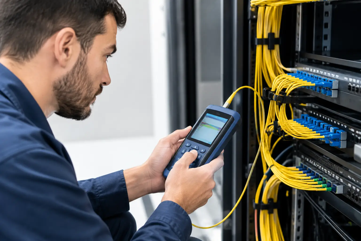
A fiber link can look finished, show a link light, and still be one dirty connector or bad splice away from an outage. That is why knowing how to test fiber links is not just a cabling task. It is an acceptance, operations, and accountability task - especially when the link supports security cameras, access control, Wi-Fi, building systems, tenant networks, or critical data environments.
A proper test proves more than continuity. It establishes that the installed fiber performs within the loss budget, is correctly identified, can support its intended application, and has documentation an operations team can use after the installer leaves. Anything less creates a familiar ownership gap: the cabling contractor says the fiber is done, the network team sees intermittent errors, and facilities is left coordinating a problem nobody owns.
Start With the Link’s Intended Use
Before anyone connects a tester, define what is being accepted. A short multimode backbone between telecom rooms is not tested and governed exactly like a long single-mode outside-plant run to a remote building. The fiber type, connector type, number of strands, link length, application speed, and expected optics all affect the test method and pass/fail threshold.
The most useful baseline is the approved design and its loss budget. That budget should account for fiber attenuation, connector loss, splice loss, and a reasonable operating margin. Do not accept a generic statement that the link is “within standard” if the actual application, component mix, or project specification calls for a tighter requirement.
Also establish the test boundary. Is the contractor certifying a permanent link from patch panel to patch panel, or a complete channel including patch cords? Both can be valid, but they are not interchangeable. A clean permanent-link test does not prove that the patch cords later installed in a cabinet are clean, correctly rated, or free of damage.
How to Test Fiber Links in the Right Order
Fiber testing works best as a disciplined sequence. Skipping ahead to a loss result can hide the root cause of a poor connection or produce a passing result that cannot be trusted later.
Inspect and clean every connector end face
Inspection comes first. Use a fiber inspection scope to examine connectors, adapters, and patch-panel ports for dust, oil, scratches, chips, or residue. Then clean the connection with tools designed for fiber and inspect it again.
The rule is simple: inspect, clean if needed, and inspect again. Do not assume a connector is clean because it had a dust cap. Dust caps collect contamination too, and a dirty mating cycle can permanently damage both connector ends.
This step is often treated as technician housekeeping. It is actually one of the highest-value controls in the process. Contamination can increase insertion loss, create reflectance problems, and cause intermittent performance that appears only after equipment is placed under load.
Verify identification, fiber type, and polarity
Next, confirm that labels match drawings and that the correct fibers are connected end to end. Verify the fiber type as well. Connecting multimode and single-mode infrastructure, using the wrong connector polish, or installing patch cords that do not match the designed system can produce confusing results and future failures.
Polarity deserves particular attention on duplex and parallel-fiber applications. Transmit must reach receive at the far end. A continuity check may prove that light travels down a strand, but it will not necessarily prove that the channel is mapped correctly for the equipment being connected.
For new construction and major renovations, compare test identifiers against the room names, rack positions, panel IDs, and strand numbers used in the turnover documents. If labels in the field do not match the record set, stop and correct the records before final acceptance. Documentation errors become expensive when a fault occurs at 2:00 a.m. and the team is tracing the wrong path.
Use continuity testing for fast fault isolation
Continuity testing confirms that a fiber is not broken and that the expected strand reaches the expected destination. A visible fault locator can help find obvious breaks, severe bends, poor terminations, and incorrect routing on short runs. It is useful during installation and troubleshooting, but it is not certification.
A visible fault locator should be used carefully and only by trained personnel. Never look into a fiber end, and do not assume a link is dark because you cannot see light. Active network optics may use wavelengths outside the visible range. Follow site safety procedures and verify whether the fiber is in service before testing.
Certify loss with an optical loss test set
For acceptance testing, an optical loss test set is the primary tool. It measures end-to-end insertion loss and typically reports link length. This is commonly called Tier 1 testing.
The technician establishes a reference using approved reference cords, then measures each fiber at the required wavelengths. For multimode fiber, the selected wavelengths are typically in the short and long operating windows for that fiber type. Single-mode fiber is normally tested at its corresponding operating windows. Test requirements should follow the project specification and the installed fiber system, not a one-size-fits-all field habit.
The result must be compared against the documented loss limit for that specific link. A pass result should identify the tested strands, direction, wavelength, measured loss, allowed loss, length, date, tester configuration, and technician. Without those details, a PDF that simply says “pass” has limited operational value.
Reference-cord condition matters. Worn, dirty, or mismatched reference cords can distort results. If readings seem inconsistent, inspect and clean first, then confirm the reference setup before declaring the installed cable defective.
Use an OTDR when the loss result needs an explanation
An optical time-domain reflectometer, or OTDR, provides a trace of events along the fiber. It helps locate connector events, splices, sharp bends, breaks, and sections with abnormal attenuation. This is commonly called Tier 2 testing.
An OTDR is especially valuable for long runs, outside-plant fiber, splice-heavy routes, and any link that fails loss testing. It can show where loss occurs, which changes the repair conversation from “the fiber failed” to “there is an abnormal event approximately this far from the telecom room.”
OTDR testing has limits. The instrument has event dead zones near each end of the fiber, so launch and receive fibers are required to accurately assess the first and last connections. Trace interpretation also requires skill. A reflective event is not automatically a failed connector, and a nonreflective event is not automatically a good splice. The trace must be reviewed alongside the loss results, route information, and installation conditions.
Do Not Confuse Fiber Certification With Network Validation
A certified fiber link can still fail to support a production service. Incorrect optics, incompatible speeds, poor switch configuration, damaged equipment ports, power issues, and network loops are outside the scope of a basic fiber certification test.
After physical-layer acceptance, validate the live service. Confirm that the intended equipment establishes link at the required speed, check interface errors and optical power levels where available, and verify that the actual application works. For a building system, that may mean confirming devices report reliably across the connection. For a tenant or enterprise network, it may mean validating throughput and error-free operation during an agreed test window.
This distinction prevents unproductive handoffs. The cabling team should own evidence that the fiber plant meets its design requirements. The network team should own configuration and service validation. Project leadership should ensure both records are connected in one turnover package rather than scattered across emails and vendor portals.
Build an Acceptance Record Operations Can Use
The test report should be part of the building’s operating record, not a file submitted once and forgotten. At minimum, retain approved drawings, fiber route information, panel schedules, strand maps, labels, loss-test results, OTDR traces where required, exceptions, repair records, and final sign-off.
Use a consistent naming convention that reflects the physical environment. A technician should be able to move from a reported switch port or device location to a rack, panel, strand, and test result without guessing. This is where one standard matters: inconsistent room names and informal labels can turn a five-minute repair into a multi-team outage.
Set a clear acceptance rule for exceptions. If a link passes but uses most of its available loss budget, document it and decide whether it is acceptable for the planned application and future growth. Passing at installation does not guarantee adequate margin after moves, adds, changes, additional patching, or aging components.
Retest When the Environment Changes
Fiber is durable, but the environment around it changes. Retest after cabinet moves, construction near cable pathways, water intrusion, rodent damage, major power events, or unexplained network errors. New patching and repeated handling also justify inspection and targeted testing.
For critical links, retain baseline results and compare later measurements against them. A rising loss trend can identify a developing connector, splice, or pathway issue before it becomes a service interruption. That is far more useful than waiting for a tenant, security operator, or building engineer to report that a system has gone offline.
The practical objective is not to generate more test reports. It is to leave every fiber path with a proven performance baseline, a clear owner, and records that make the next decision faster when conditions change.