
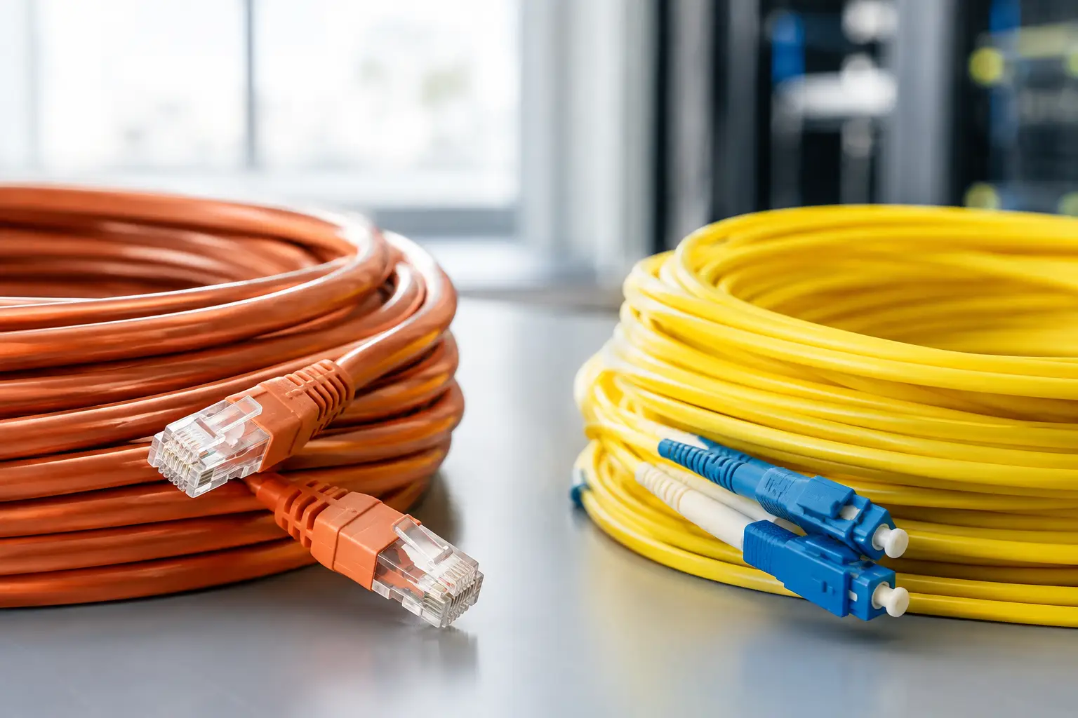
A cable choice made during design can affect building operations for decades. Copper versus fiber cabling is not simply a speed comparison. It determines where network equipment can sit, how devices receive power, how far services can extend, what interference risks must be managed, and how difficult future expansion will become.
The failure usually starts when the decision is treated as an installer preference. One team selects cable based on a drawing, another selects switches later, and a third inherits the site without test records or accurate pathways. The building opens with connectivity, but not with a managed infrastructure standard. That is how minor moves become outages and capacity upgrades become invasive construction work.
For commercial owners and operations leaders, the right question is not, “Which cable is better?” It is, “What operating requirement must this pathway support, and who will validate it through turnover?”
Copper Versus Fiber Cabling Is an Operating Decision
Copper and fiber solve different problems. Copper is often the practical choice from a telecommunications room to desk outlets, access points, cameras, access-control devices, sensors, and other endpoints. It carries data and, in many applications, electrical power on the same cable. That combination reduces the need for local power supplies and gives facilities and security teams a central point for backup power management.
Fiber is designed for distance, high capacity, electrical isolation, and resilience between rooms, floors, buildings, and major distribution points. It does not deliver operating power to an endpoint, but it can move large volumes of data over distances that make copper impractical. It is also unaffected by electromagnetic interference, which matters near electrical distribution equipment, motors, elevators, industrial systems, and other noisy environments.
Neither medium eliminates the need for good design. A fiber backbone with undersized pathways is still constrained. Copper installed too close to sources of interference can still create service issues. A well-performing network depends on the cable, the containment system, room locations, equipment design, grounding practices, testing, documentation, and accountable acceptance process.
Where Copper Is the Better Fit
Copper remains the normal horizontal cabling medium in many commercial environments because it supports common endpoint distances and can power devices. That makes it especially useful where the endpoint is active, distributed, and likely to change over time.
Consider an office floor with wireless access points, desk connections, door controllers, cameras, room schedulers, and building sensors. Running a separate electrical circuit to every device can add coordination, maintenance, and restoration complexity. Properly designed copper cabling can support connectivity and centralized power delivery, allowing critical network rooms to be backed by conditioned power and monitored during an outage.
That benefit comes with limits. Power delivery creates heat, especially when cable bundles are densely packed. Higher power demands, poor bundle management, incorrect connectors, or inadequate pathway capacity can reduce performance and complicate maintenance. The design team must account for cable category, bundle size, ambient conditions, pathway fill, patching practices, and the actual power requirements of the devices being installed.
Copper also has a distance ceiling for standard horizontal applications. It works well when telecommunications rooms are placed intentionally. It becomes a poor workaround when room placement is an afterthought and teams try to stretch service across an oversized floor plate, parking structure, warehouse, or campus.
Where Fiber Is the Better Fit
Fiber should be the default consideration for backbone paths, long-distance links, inter-building connections, data-intensive aggregation points, and locations exposed to electrical interference. It gives a building more latitude to place network rooms where they can be secured, cooled, powered, and maintained instead of forcing equipment into unsuitable closets simply to stay within copper distance limits.
For multi-floor buildings, fiber between distribution rooms supports capacity growth without repeated recabling of vertical pathways. For campuses and separate structures, fiber avoids the electrical grounding and surge exposure issues that can arise when conductive cabling crosses between buildings. It also creates a cleaner separation between equipment areas with different electrical conditions.
Fiber is not automatically the right answer at the edge. It requires compatible electronics at each end, disciplined connector handling, clean termination practices, and technicians who understand testing results rather than simply reporting a pass. It also cannot power a camera, access point, or controller. If a design replaces copper with fiber to reach a remote endpoint, the team must define how that endpoint receives reliable power and how it behaves during a power interruption.
The practical pattern is often fiber to a local distribution point and copper from that point to powered endpoints. The governing issue is not the media transition itself. It is whether the local enclosure, room, or cabinet has secure access, cooling where needed, power protection, grounding, capacity, labeling, and an assigned owner.
The Hidden Risk Is Usually the Handoff
Cabling decisions often fail at the boundary between construction and operations. The installer may complete the work to a narrow scope. The network team may install electronics later. Facilities may inherit closets without knowing what serves them. Security may add devices after occupancy. Each party can say its individual task was complete while no one can confirm the operating condition of the full system.
That gap is costly during an incident. When a camera drops offline, teams need to know its serving room, pathway, patch field, switch port, power source, and upstream connection. If those records are incomplete, diagnosis turns into a search through ceilings, closets, and disconnected spreadsheets. Downtime grows because ownership was fragmented before the first fault occurred.
Treat copper and fiber as managed assets, not concealed construction materials. Every pathway, cable, termination point, enclosure, and room should be identified in a system of record that operations can use. The record should connect physical infrastructure to the business service it supports, whether that is tenant connectivity, building controls, security coverage, or a critical application environment.
Specify for the Next Change, Not Only Day One
A good cabling specification starts with the services the building must operate and the changes it is likely to absorb. A speculative office floor has different needs than a medical facility, distribution site, mixed-use property, or controlled data environment. The correct design depends on endpoint density, expected device power, floor area, room placement, growth plans, outage tolerance, and physical conditions.
Ask whether the design has enough backbone capacity for additional tenants, wireless growth, new cameras, and building-system connections. Ask whether telecommunications rooms are sized for future equipment rather than only the initial rack count. Ask whether major pathways have accessible capacity after the first installation. If the answer is no, the project may meet a current drawing while transferring expensive constraints to the operating team.
This is also where owners should resist false simplicity. Selecting only fiber because it has more capacity can create a power problem at the edge. Selecting only copper because it is familiar can limit reach, increase interference exposure, and force poorly located rooms. The right architecture usually uses both media deliberately, with clear demarcation points and documented responsibilities.
Acceptance Testing Must Match the Design Intent
A cable test report is valuable only when it proves the installed system supports its intended use. Copper testing should validate the installed channel or permanent link against the specified performance level, with records tied to unique cable identifiers. Fiber testing should confirm continuity and loss performance, while more detailed traces may be necessary where length, splice quality, or fault location matters.
Test results should not arrive as a generic file at the end of the project. They need to be reviewed against drawings, labels, room schedules, and the final network design. Missing identifiers, unexplained exceptions, incomplete fiber strands, mislabeled ports, and inaccessible pathways should be corrected before acceptance, not converted into a future maintenance problem.
Final turnover should include accurate drawings, pathway information, cable schedules, test records, room inventories, labeling conventions, and escalation ownership. The operating team should be able to trace a service from the endpoint to its network room and backbone connection without relying on the installer’s memory.
The cable behind the wall will be easy to ignore right up until a tenant move, device expansion, water event, or outage exposes the design. Specify the medium for the real operating environment, require one standard across the project, and make final acceptance prove that the infrastructure can be supported long after construction crews leave.